Too late for a spoiler alert, this article is going to describe the benefits of a patchbay and why for most applications choosing half normal is a good bet. If you have a music studio, regularly find yourself plugging and unplugging equipment and you don’t know your normal from half normal then all you need is this article. And a patchbay. Essentially utilitarian the patchbay is an inexpensive piece of equipment that is incredibly useful and also manages to be fun and inspiring, helping you stay in the flow rather than wrestling with spaghetti tangled leads.
My mixing desk has a number of mono channels (complete with full e.q. and effects sends) and some simpler stereo line only channels. Over the years I used up all the inputs and added a simple line mixer to accommodate plugging in more instruments. Mono instruments were assigned to the fully equipped mono channels and stereo equipment to the simpler stereo channels in a semi-permanent routing. I say semi-permanent because in reality I was often keen to make use of the e.q. on the fully featured mono channels so found myself unplugging the instrument in that channel (often losing the lead down the back of the desk) in order to replace it with another instrument. Often I unplugged the wrong thing, disturbed something else or had to go armed with a torch to retrieve leads lost under the desk.
After doing some research I decided to install a patch bay. Now whenever I want to route a signal from one point to another all I have to do is to go to the patchbay and direct it to another part of the patchbay. In the rest of the article I’ll explain my planning and the rationale for wiring the patchbay as half normal, taking the opportunity to explain some of the terminology on the way.
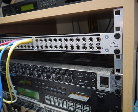
You can see the installed patchbay in the photo below. The photo shows the front of the patch bay. Around the back of the bay are corresponding numbered sockets. In patchbays there is a relationship between the front and corresponding rear socket and also between the top and bottom row. I’d recommend buying a patchbay that has switches so that you can configure the relationships between the front and back and rows as suits you. The whole purpose of a patchbay is to simplify swapping your signal routing around and for this reason, however you chose to set yours up you’ll want to have the rear connections pretty much permanent with the front panel used to swap routing around at will.
Through Mode
In this arrangement the signal presented to the rear socket appears in the corresponding front socket. Similarly, you could connect the rear socket to the input of something like a mixing desk or effect box.
Initially I thought this would be useful for my situation. I’d take the leads from the back of the patchbay and connect them to the mixing desk, plugging the instrument leads into the front of the patchbay, then if I wanted to swap anything around all I would need to do is plug the instrument lead into the front of the patchbay and viola, it would be routed to the mixing desk. However all this would achieve is move the mess of leads connected to the mixing desk to the front of the patchbay, simply relocating the problem. How could the patchbay be set up in a semi permanent wiring arrangement that would allow me to swap stuff around with the minimum of fuss?
Half Normalled
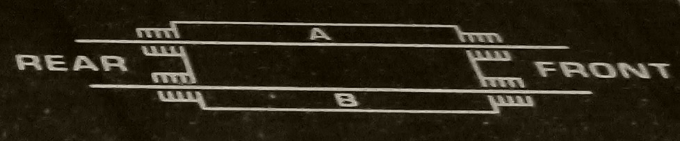
In this configuration the rear of the patchbay is wired so that the top row is routed to the bottom row. By convention signals into the patchbay are routed to the top row and signals out come from the bottom row. Therefore all I needed to do was set up the bottom row so that the leads from the back of the bay went to the inputs of the mixing desk. The instruments were plugged into the rear top row. This replicated the original routing arrangement. With a half normal scheme the signal going into the rear will be available in the corresponding front socket. By connecting a lead into the front top row you can route it to a different location by plugging it into the bottom row.

In the picture below the signal from the top row sockets 9, 10, 11 and 12 are routed to the bottom row 3,4, 5 and 6. In a half normal scheme the connection between the top row remains connected to the bottom row unless something is plugged into the bottom row.
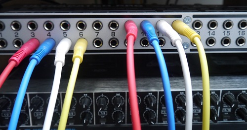
So by default top row 3, 4, 5, 6 would be connected to bottom row 3, 4, 5 & 6, however in the patch shown this connection has been broken by connecting the leads to the bottom row. However the routing between top and bottom row 9, 10, 11 & 12 remains intact as nothing is plugged into the front bottom row of 9, 10, 11 & 12.
The advantage to this arrangement is that
- it allows for routing the same signal to two destinations at once
- you could use this routing to take the signal into an effect box and route it elsewhere which can be handy for applications like parallel compression or when working with signal processesor without a wet / dry balance.
Plugging it all in
So in the end I opted for a half normal arrangement. I purchased a couple of wiring looms (bundles of cables with multiple connections) then connected the rear bottom row to the inputs of the mixing desk. Coloured leads helped keep track of things, something I’d also recommend for the patch leads.
I opted for a cheap patchbay that lets the user configure the connections at a flick of a switch – this is the kind of thing you do once, then forget about, but at least I didn’t have to get out the soldering iron. The leads from the instruments were connected to the top row and connectors to the desk in the bottom rear row.

As you can see the wiring to the mixing desk is now clean – no more losing cables round the back.
Final thoughts
For the sake of completeness I’ll also mention the fully normalled configuration. This is similar to the half normalled arrangement, except that plugging a cable into the front to row breaks the connection to the bottom row.
I could further develop the patching abilities by adding another patchbay as in my current arrangement the effect sends are permanently plumbed to signal processesors without going near a patch bay. By adding another patchbay I could route each effect send from the mixing desk to the top rear row of the patchbay, then using semi normalled routing take the signal from the rear row to an effect processor. Effect processor out to another top rear row connector. Bottom rear row is the effect return bus to the mixing desk. This would allow greater flexibility e.g. serial chains, even feedback loops, or using the signal processesor as insert effects rather than standard effect bus effects.
Once you’ve done the original thinking and setting up, patch bays make life simpler and open up a world of creative possibilities.